
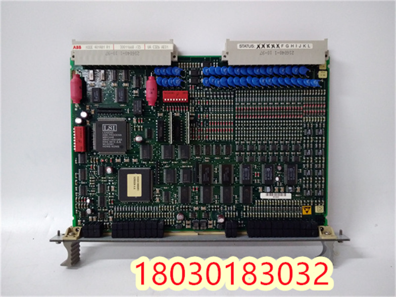
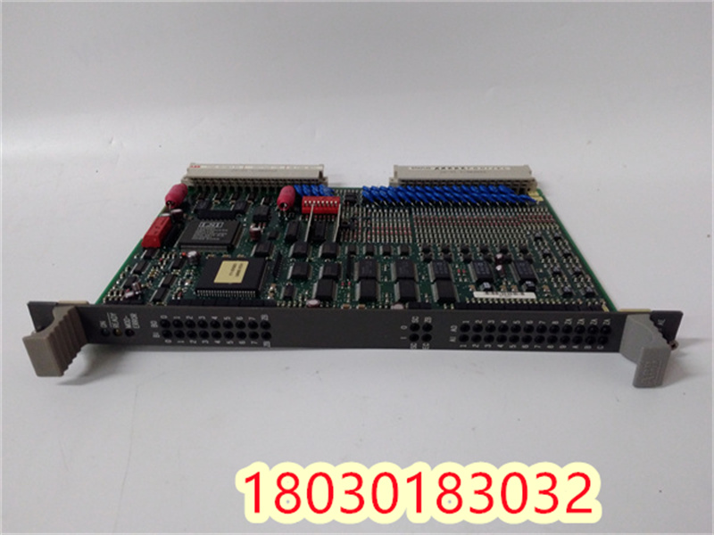
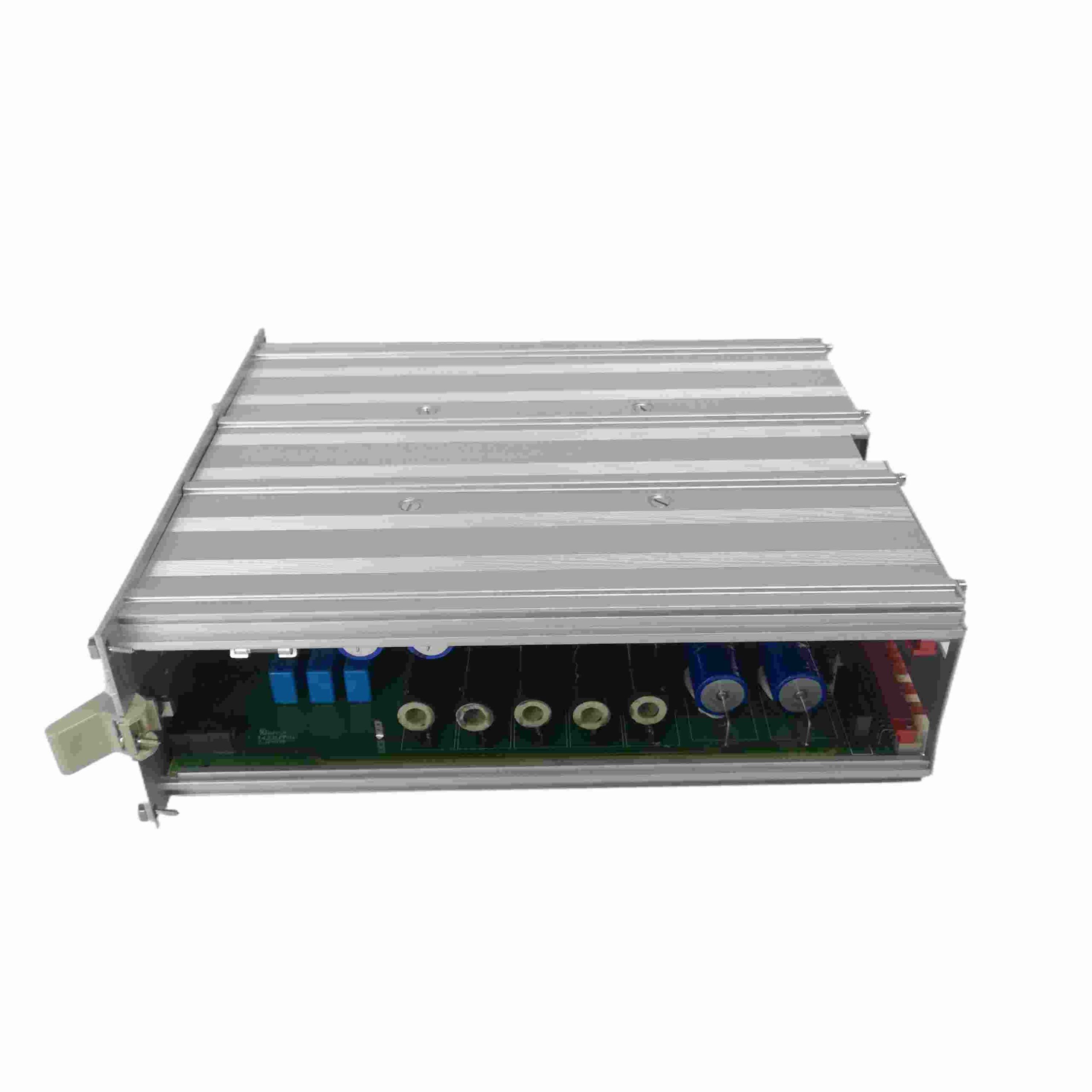
Description
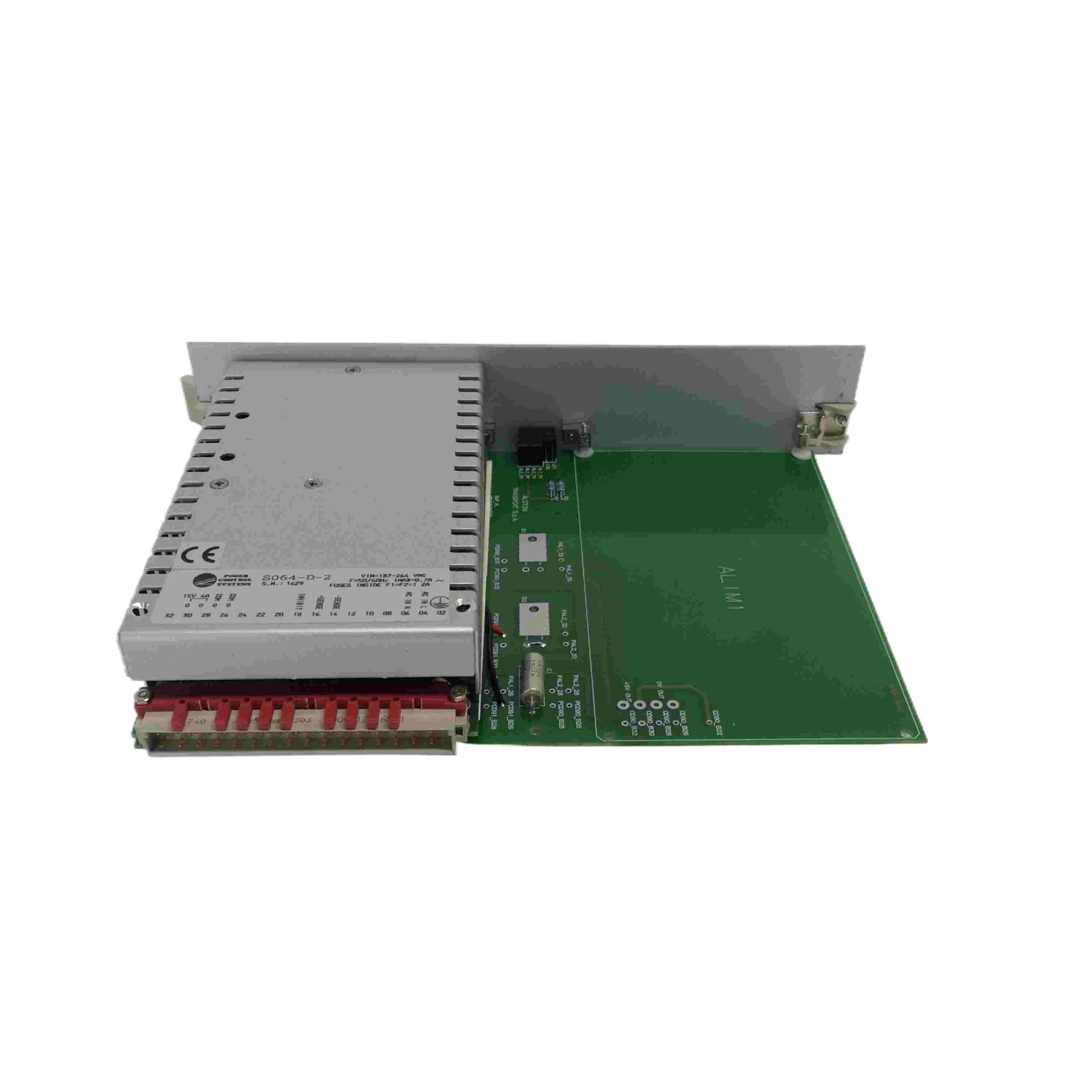
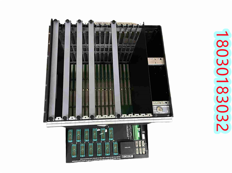
To connect the UAC326AE ABB excitation control card to the positive power bus and module input, follow these steps. Please note that these steps are based on general guidelines and may vary depending on the specific device model, configuration, or manufacturer’s specific requirements. Therefore, it is recommended to refer to the technical manual of the UAC326AE or contact the manufacturer for accurate guidance before making a connection.
Connection step
Determine connection position
First, determine the UAC326AE ABB excitation control card needs to be connected to the positive power bus and which module inputs. This usually involves understanding the hardware configuration of the control card and the power and signal lines required.
Prepare connection material
Make sure you have the proper connection materials such as cables, adapters, connectors and check that they are in good condition.
Connect the positive power bus
Connect the positive power bus directly to the control card of the UAC326AE using the appropriate cable.
Ensure that the cable is securely connected, that the insulation is not damaged, and that the relevant electrical safety standards are met.
Link module input
For each module input that needs to be connected, connect them to the control card of the UAC326AE using the appropriate cable.
Often, these cables come with a specific color code or label to make them easier to identify.
Install fuse (if required)
In order to protect the circuit and equipment, the appropriate fuse specifications are selected and installed according to the requirements of the UAC326AE control card and related modules.
Grounding and shielding
Ensure that all connected lines are properly grounded and use appropriate shielding measures to reduce electromagnetic interference (EMI).
According to relevant standards and guidelines, proper grounding and shielding can ensure the stable operation of the equipment.
Check connection
After the connection is complete, carefully check that all lines are properly connected and that there are no exposed electrical conductors.
Ensure that all connections are secure and reliable, with no loose or false connections.
Power Settings
Set the correct power supply according to the power requirements of the UAC326AE control card and related modules.
Ensure that the power supply is stable and complies with relevant specifications and standards.
Testing and debugging
Once all connections and setup are complete, test and debug to make sure the device is working properly.
Check that signal quality and power supply meet requirements and ensure that all modules are working properly.
Matters needing attention
Before making any electrical connections, ensure that the power is disconnected and that the relevant electrical safety procedures are followed.
If you are not familiar with electrical connections or are unsure how to make them, seek professional help.
Always refer to the technical manual of the UAC326AE or the guidance provided by the manufacturer to ensure the correctness and safety of the connection.
| CI855K01 |
| REXROTH MHD093C-058-PG1-AA |
| DSQC202 |
| KUKA KPS-600/20-ESC |
| A-B 1756-L73 |
| EMERSON VE3008 |
| 5SHX0660F0001 |
| ROCKWELL T8231 |
| GE IC698CPE020 |
| bENTly 3500/22M |
| KUKA KCP2 |
| INIIT13 |
| GE IC698CPE020 |
| BAUMULLER BKF12/120/400/2002 |
| GE IC698CPE020 |
| A-B 1771-IFMS |
| TDI SPS5710 |
| TDI SPS5710 |
| ICS TRIPLEX T8310 |
| SCHNEIDER 140CPU67160 |
| GE IC698CPE020 |
| GE IC698CPE020 |
| MOOG D136E001-001 |
| NTCF22 |
| TDI SPS5785 |
| GE IC695CRU320 |

Reviews
There are no reviews yet.