Description
GE IS220PVIBH1AL Vibration I/O Pack
Description:
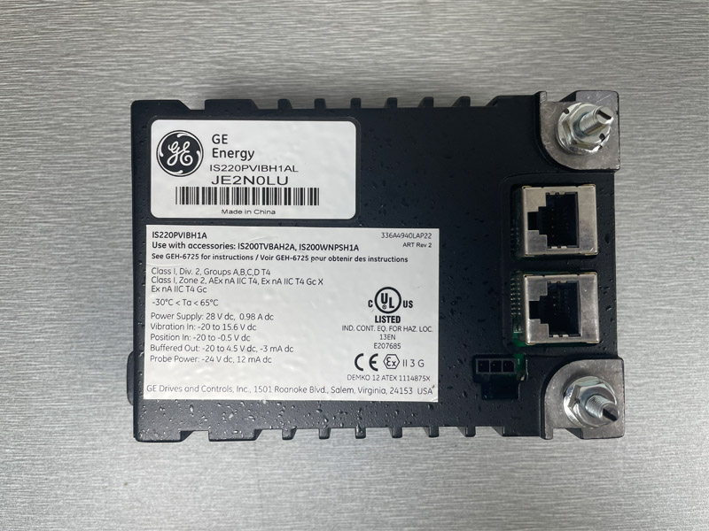
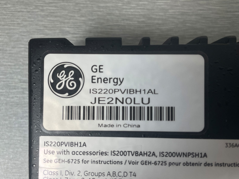
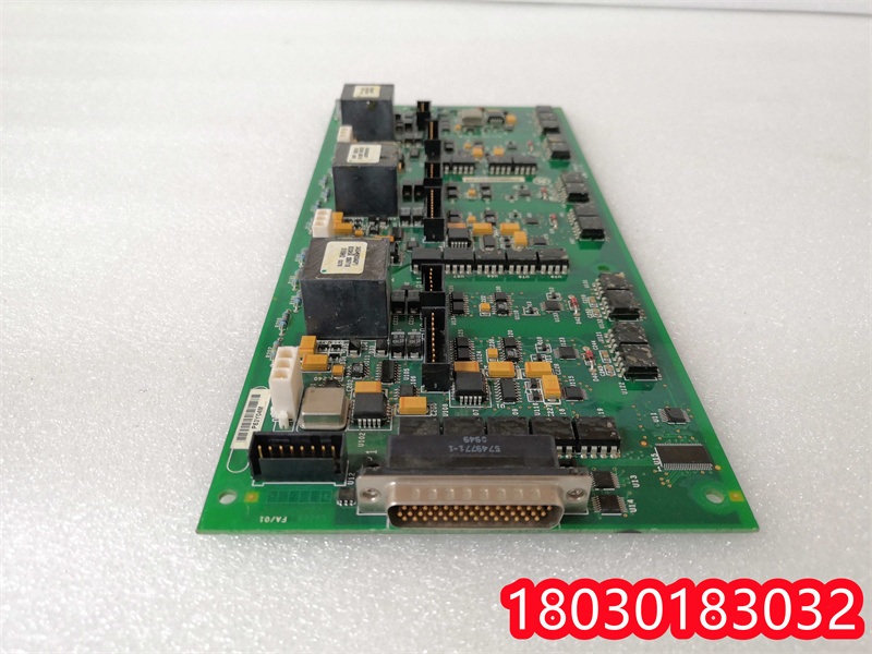
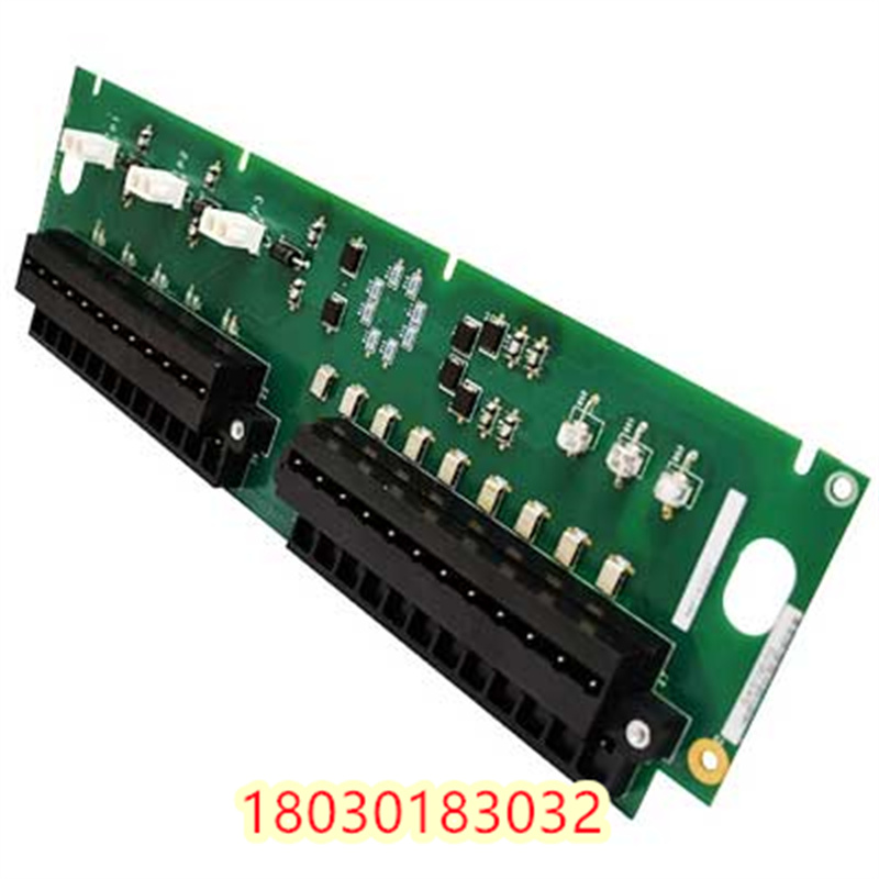
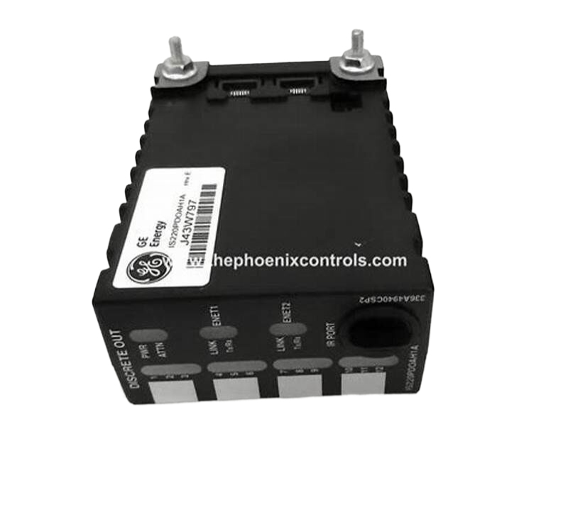
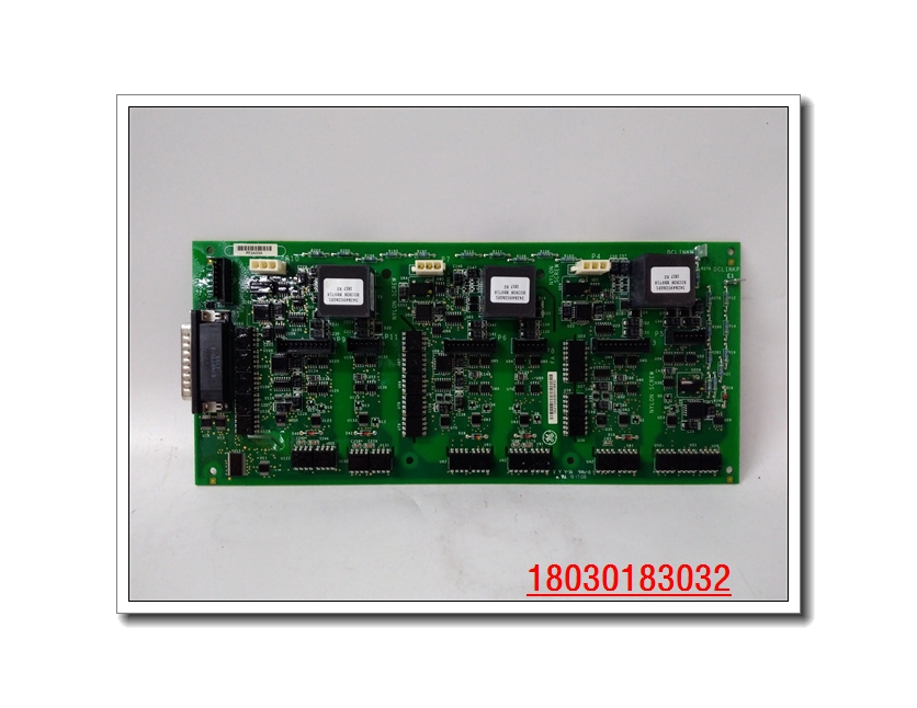
IS220PVIBH1AL is manufactured by GE, it is belong to Mark Vie series Vibration I/O Pack. The IS220PVIBH1AL (PVIB for short) vibration monitoring module contains a local processor and data acquisition board, which are housed in an I/O pack. Either one or three I/O packs can be mounted on the TVBA terminal board, to provide either Simplex or TMR module redundancy. The TVBA provides two 24-point, barrier-type terminal blocks that accept two 3.0 mm2 (#12AWG) wires with 300 V insulation and spade or ring type lugs.
Captive clamps are provided for terminating bare wires. Signal flow between the terminal blocks and the I/O packs is conditioned with passive suppression circuits and electromagnetic interference protection. In addition, a pull-up bias is applied to signals for open circuit fault detection.
The PVIB can monitor 13 sensors, and has the flexibility to mix sensor types based on specific channel configuration and PVIB processor type. The I/O pack has two RJ-45 Ethernet connectors, one 3-pin power input, and a DC-37 pin connector that connects directly to the TVBA terminal board. Visual diagnostics are provided through indicator LEDs.
IS220PVIBH1A can be mixed on a TMR module. In this mixed TMR configuration, all three I/O packs must be upgraded to firmware version 5.01 or later. In addition, there are manual steps needed to correct some existing configuration because of the additional GAP12 capabilities that are introduced in firmware version 5.01.
Specifications:
Input Signal Bandwidth: 1150 Hz
Number of Channels: 13 sensor inputs are supported.
Buffered Outputs (only with TVBAH2A and TVBAH2B): Amplitude accuracy is 0.1 % for signal to GE Bently Nevada 3500 system.
A -11 V dc +5% bias is added to output when a seismic probe used.
Sinks a minimum of 3 mA when interfacing a velomitor.
Probe Power: -24 V dc from the -28 V dc bus, from the WNPS daughterboard
Each probe supply is current limited with 12 mA load per transducer
Open Circuit Detection: Open circuit is defined as a gap voltage that is
> 1.0 V for Proximity, Accelerometer, Keyphasor, and CDM BN at terminals
> -1.0 V for Velomitor at terminals
< -1.0 V for CDM PCB at terminals
<-3.0 V for Seismic at terminals
Common Mode Voltage:Minimum of 5 V dc
CMRR at 50/60 Hz:-50 dB
Dimensions: 8.26 cm high x 4.19 cm wide x 12.1 cm deep (3.25 in x 1.65 in x 4.78 in)
Technology: Surface-mount
Ambient rating for enclosure design: from -40 to 70°C (-40 to 158 °F)





Reviews
There are no reviews yet.